Star Electronics Simbol Simbol dalam PCB / Skema
The symbol for an ohm is the Greek letter Omega, which looks like this: Ω. 100MΩ translates to 100 megaohms. Other easy-to-identify components include oscillators (cylinders or boxes typically marked with X or Y), transformers (T), diodes (D), and relays (marked as K). Now look to see if the board has a fuse.
P8155 footprint, schematic symbol and 3D model by Intel
It's also a standard glyph in a suitable font, at code point 26A0, looking like this: So I did a little experiment. I copied that symbol and then opened my layout, switched to F.Silk, selected the text tool, pasted the symbol in, changed the font size to 10mm width and height, selected a font at random DejaVu Sans, and voila, the symbol appeared on my layout.
How to learn basic Electronics ? TjkTechnology, Electrical and Electronic Engineering
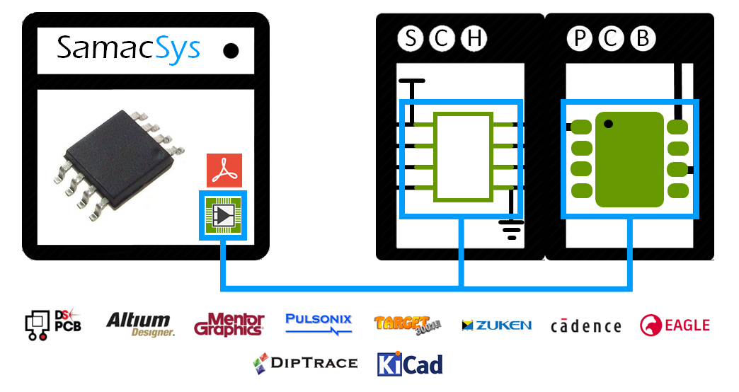
What PCB design formats are supported? CUI Devices' PCB symbols and footprints can be downloaded in all major PCB design formats, including Altium, Eagle, KiCad, OrCAD and Allegro, PADS, and PCB123. Simply select the format at the top right-hand corner to start downloading for the desired PCB design tool. CUI Devices' PCB footprint viewer module.
Star Electronics Simbol Simbol dalam PCB / Skema
Join SnapMagic Search today. Design faster with SnapMagic Search. Download CAD models for millions of electronic components, including schematic symbols, PCB footprints, and 3D models.
Power Pcb Layout Guidelines Design Talk
29 votes, 16 comments. 728K subscribers in the AskEngineers community. Engineers apply the knowledge of math & science to design and manufacture…
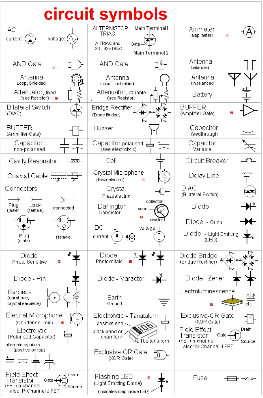
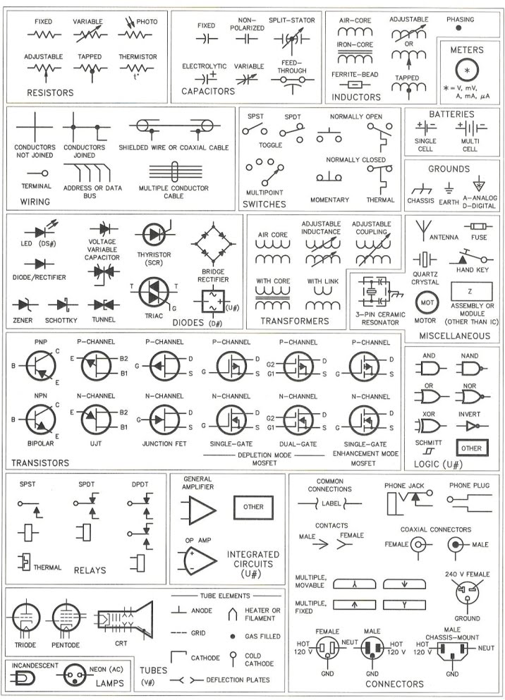
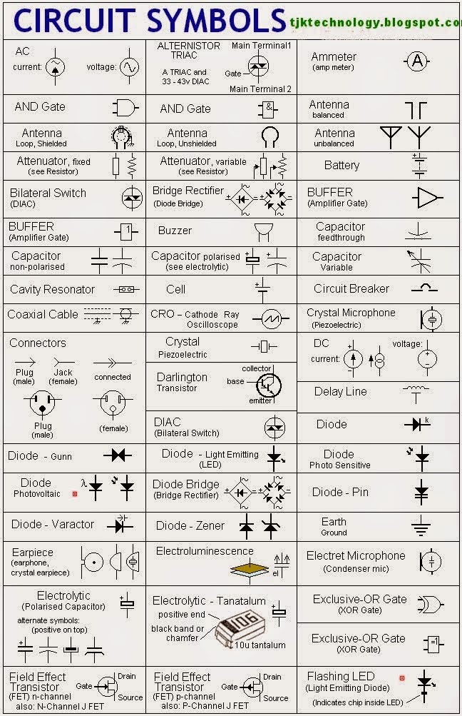
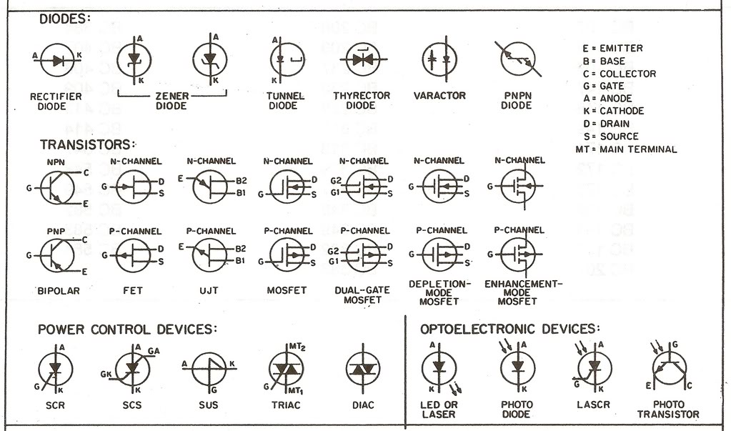
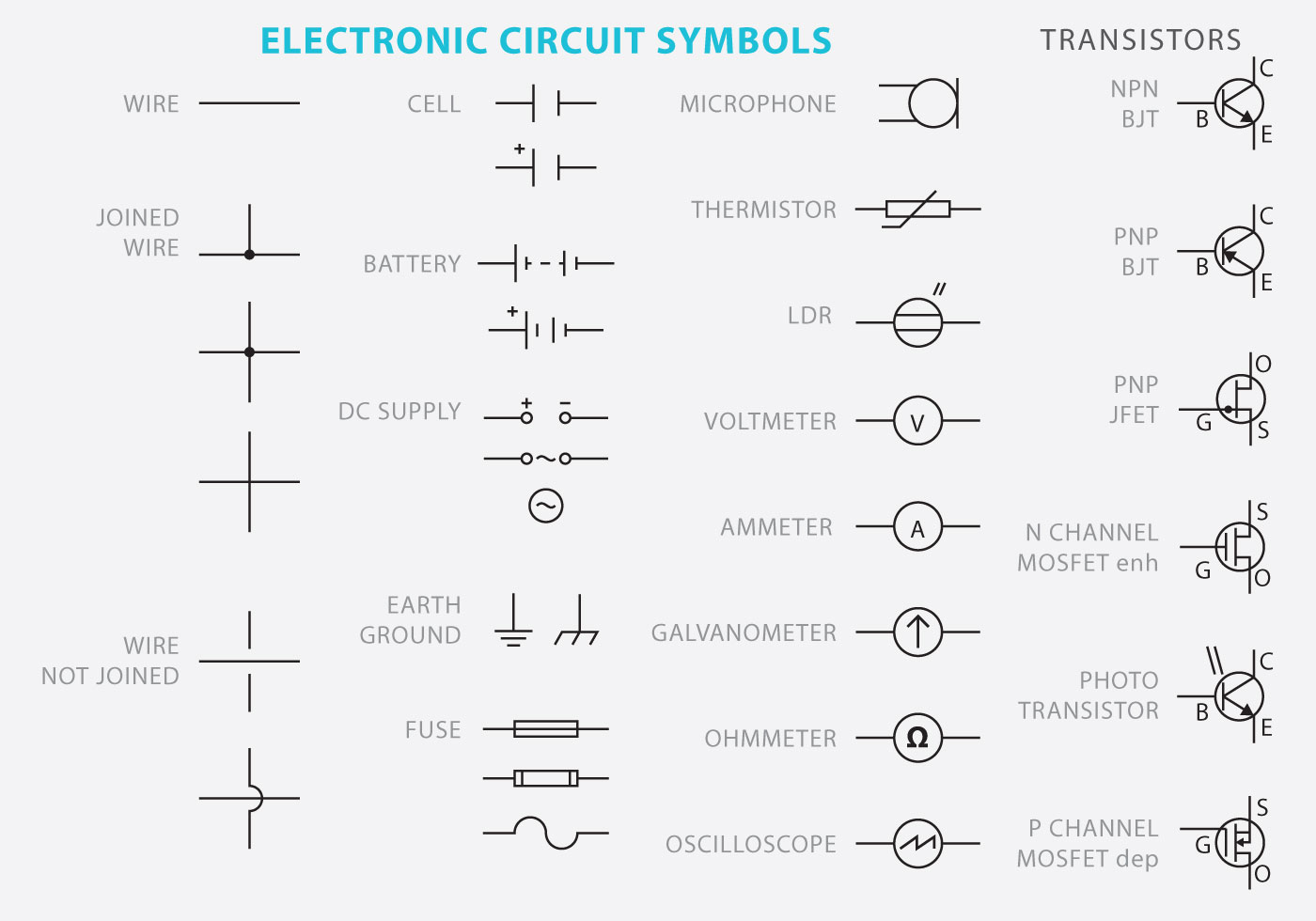
Electronic Schematic Symbols Chart
Free Design Resources. Ultra Librarian is the worlds largest online - and always free - PCB CAD library. Build products better, faster, and more accurately with easy access to vendor-verified symbols, footprints, and 3D models. Register today to start searching the right components for your next design.
Download Quality PCB Footprints and Schematic Symbols
Specializing in all aspects of drywall and carpentry. We provide the highest quality of service to our customers through our professionalism, extensive knowledge, attention to detail and focus on safety for every project, large or small. MBE Certified. Learn More.
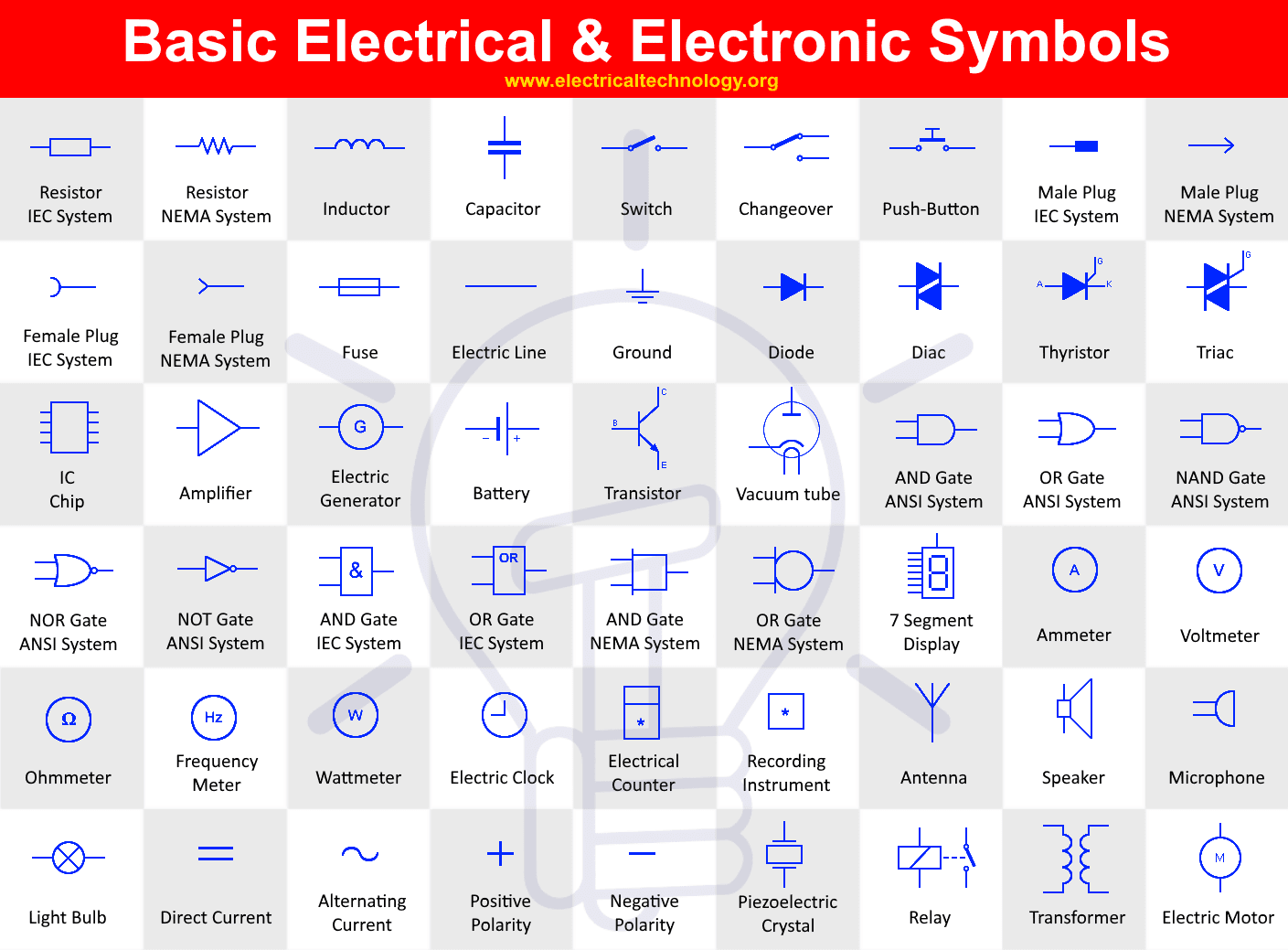
Electrical Components Schematic Symbols
Following conventions apply to symbol names: Language must be American English (en_US) Title case (e.g. "Capacitor Bipolar" instead of "Capacitor bipolar") Singular names, not plural (e.g. "Diode" instead of "Diodes") If reasonable, start with the generic term (e.g. "Supply GND" instead of "GND Supply") to improve navigation in sorted lists.
PCB Library Standards Symbol, Footprint, 3D Component Models
1 Answer. I don't know what it's doing on a circuit board, but I've see that symbol on lamps. It means "if you break the glass window, replace it with a new one." I've generally seen it on 230VAC, 500 watt halogen flood lights that have a tube light emitter behind a thin glass panel. The light will work fine without the glass panel, but is a.
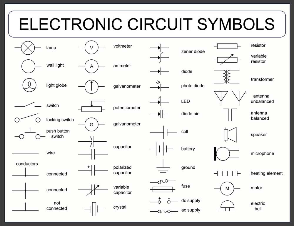
Electronic Schematics Symbols And Meanings
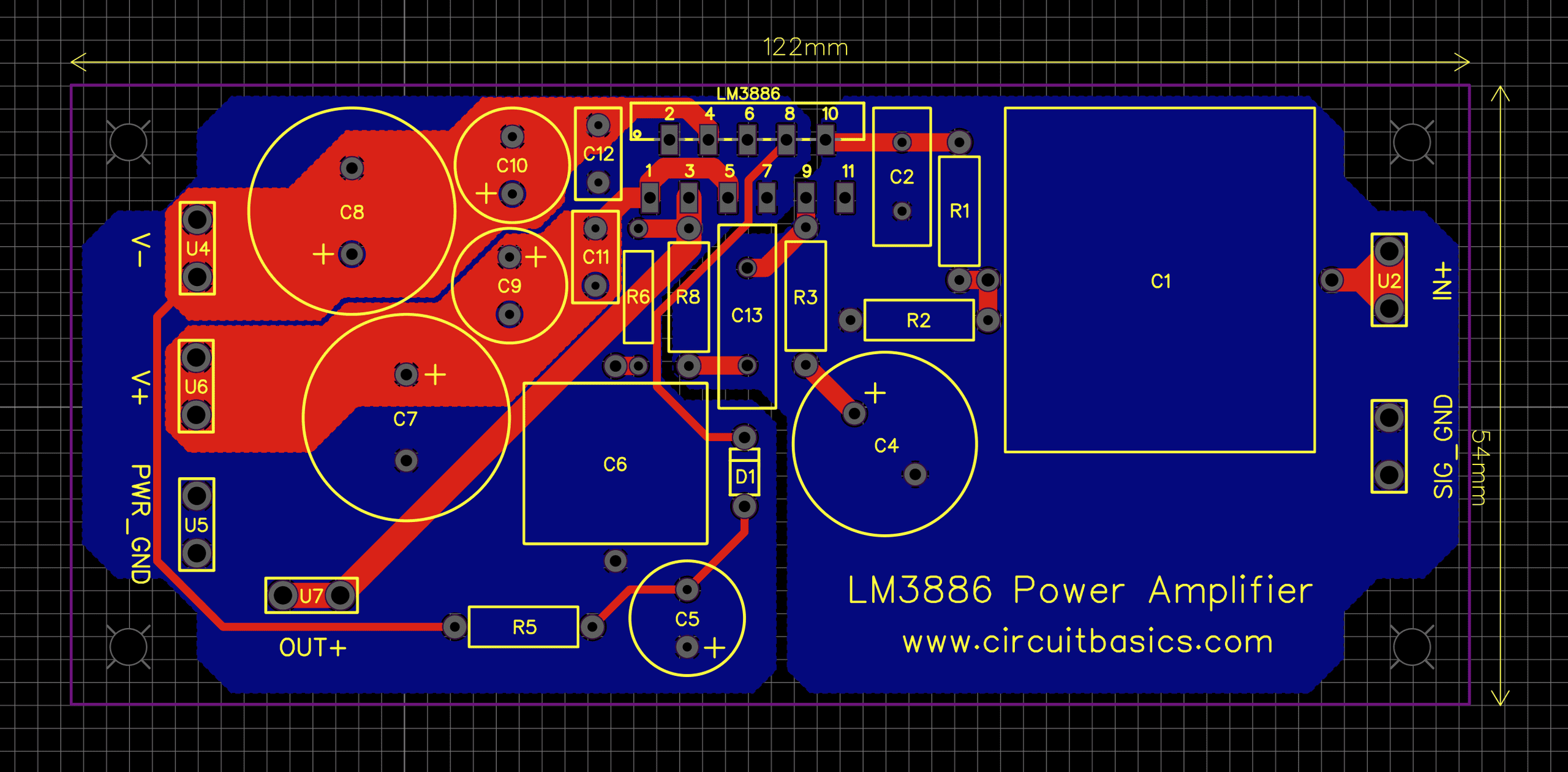
A pcb circuit board symbol is a graphical representation used in the schematic design stage of a PCB layout process. It represents the electrical components and their connections that will be assembled on the PCB. In the circuit board industry, the symbols used for circuit and identification purposes are commonly referred to as "silkscreen.
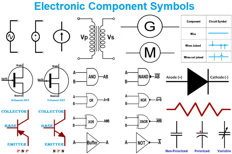
Basic Electronic Component Symbols that Every PCB Design Engineer Should Know
Altium Designer is the only program that gives designers CAD data for components and visibility in the electronics supply chain in the same application. Altium Designer makes managing electronic symbols library creation simple with a complete set of supply chain tools. Instead of cobbling together symbols from your old libraries or using a 3rd.

Standard electrical circuit symbols Stock Image T356/0593 Science Photo Library
The process of designing a PCB starts from understanding the circuit schematics and proceed with converting the schematics into a PCB Layout. To understand the schematics, any designer needs to know the circuit symbols for all basic components. If you are a beginner who is just getting started, then this article will help you to understand all the basic component symbols that you will find on.

Schematic Symbol Reference Guide PCB Coaster Etsy
They are excellent for a multitude of applications due to their capacitance, voltage, and temperature ranges. 3. Mica, Glass, and Other Fixed Capacitor Symbols. For their stability and durability, electronic circuits use mica, glass, and other permanent capacitors.

15+ Simbol Komponen Elektronika Lengkap Beserta Fungsingnya
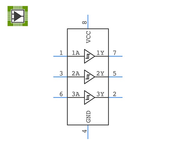
May 22, 2023. This is a guide on how to read PCB schematics. A PCB schematic is a circuit diagram designers use in the first stage of the board design process. And the core components of these schematic diagrams are unique circuit symbols that all designers globally can understand. So knowing these schematics is paramount.
PCB Schematic A 2D Diagram for Component Functions and Connections
\$\begingroup\$ A flag states that the answer has been downvoted because it's incomplete. I understand that you've not completed it because you're quoting this copyrighted work under the Amount and Substantiality Fair Use exception.I'd upvoted you before the downvote or flag, your net rep is +18 for this answer.
Guide Electrical & Electronic Circuit Symbols r/electricians
A printed circuit board (PCB) is a board made of insulating material like fiberglass with copper tracks printed on it to connect electronic components. PCBs provide the electrical connections between components in an electronic device like computers, mobile phones, appliances etc. PCB design involves creating schematics and layouts to represent the circuit connections. PCB symbols […]