Wiring A Compressor
A compressor is a vital component in an air conditioning system that pressurizes the refrigerant gas, providing cooling air through the vents. The compressor has several wires running to different electrical parts inside the unit, including switches, thermostats, and the main power supply. Many manufacturers provide a detailed wiring diagram.

Ac Compressor Fan Wiring Diagram Focus Wiring
The Ac Compressor Wiring Diagram Pdf is a useful tool in providing an understanding of the electrical components of an AC system, including the compressor, condenser, fan, and other related components. The Ac Compressor Wiring Diagram Pdf can be found online and downloaded for free. It provides detailed diagrams of the various connections and.
Compressor Motor Wiring Diagram Wiring Diagrams Hubs Compressor
Understanding the AC compressor wiring diagram is an important part of installing or repairing an air conditioning system. Knowing how to interpret the diagram and properly connect the components will help ensure that your system runs efficiently and safely. Taking the time to do this step correctly will save you time and money in the long run.

AC compressor not engaging help needed MercedesBenz Forum
How to wire air conditioner compressor. This video shows you how to wire an HVAC ac compressor. I go over the location where each wire needs to go, where the.
Auto Ac Compressor Wiring Diagram Cadician's Blog
Basic Steps for Wiring an Air Conditioner. Run electrical cable from the service panel to an air conditioner disconnect switch near the A/C unit and connect it to a new circuit breaker in the panel. Turn the breaker off. Prepare a length of cable to run from the disconnect switch to the A/C unit's control panel.
Auto Ac Compressor Wiring Diagram Wiring Diagram
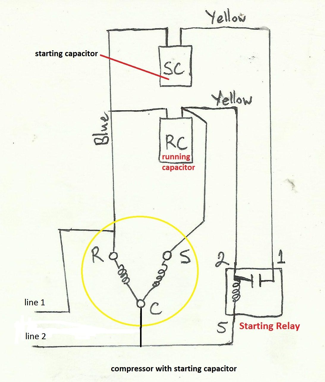
How to use the wiring diagram to locate compressor start, common, and run windings for trouble shooting a system that is not wired correctly. Also how to pro.

Aircon Compressor Wiring Diagram
The first step in wiring a 3 phase AC compressor is to gather all the necessary tools and materials. You will need a voltage meter, wire strippers, electrical tape, wire nuts, and the wiring diagram for your specific compressor model. It's important to have a clear understanding of the wiring diagram, as it will provide you with the necessary.
Ac Compressor Wiring Diagram Diagram Stream Vrogue
Importance of Correct Wiring. Think of the wiring process as a delicate dance where each step is crucial to the overall performance. If the AC compressor capacitor isn't wired correctly, the AC system won't operate efficiently, if at all. Incorrect wiring can prevent the compressor from starting or cause it to run in a way that's not energy-efficient, resulting in poor cooling.

Air Conditioner Compressor Wiring
Check the wiring diagram to ensure that the wiring is correct and that all the terminals are properly connected. Start by connecting the wires to the compressor, then the fan motor, then the thermostat, and finally the condenser unit. Make sure that all of the connections are properly insulated and that the electrical connections are secure.
Air Conditioner Compressor Wiring Diagram
Think of a wiring diagram as a roadmap or, better still, a satellite view of a city with each street representing a wire. This bird's eye view shows how different components of the AC unit, like the compressor and capacitor, are interconnected. Following this roadmap will enable us to wire the AC compressor capacitor accurately.

Air Conditioner Compressor Wiring Diagram Wiring Flow Schema
Step 2: Connecting the Red Wire. Step 3: Connecting the White Wire. Step 4: Finishing the Installation. Three-Phase AC Compressor Wiring Process. Step 1: Locating the Compressor's Wire Terminal. Step 2: Connecting the Power Wires. Step 3: Finishing the Installation. Troubleshooting Common AC Compressor Wiring Issues.

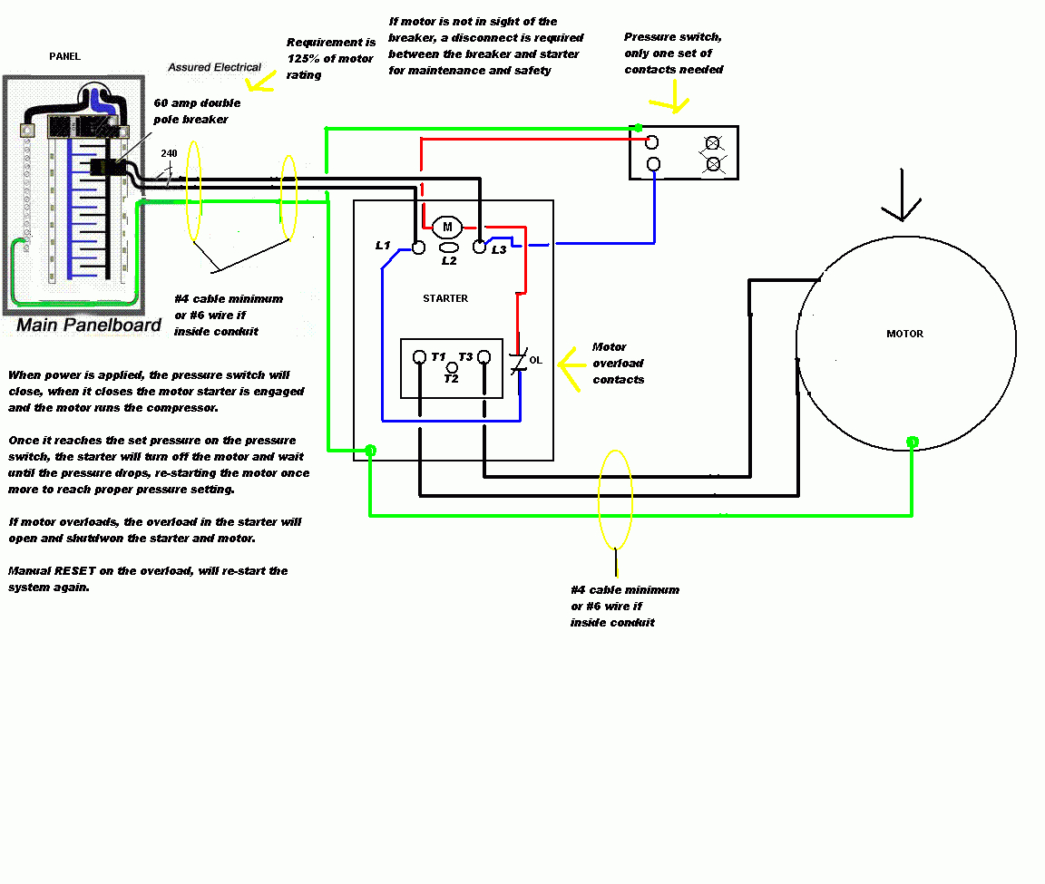
Unique Wiring Diagram for Air Compressor Pressure Switch Air
Ac Compressor Wiring Diagrams provide valuable information for homeowners, electricians, and technicians who need to repair or install air conditioning systems. The diagrams provide details such as the correct wire size, voltage rating, and color coding for each component of the system. Knowing how to read and interpret a wiring diagram is an.

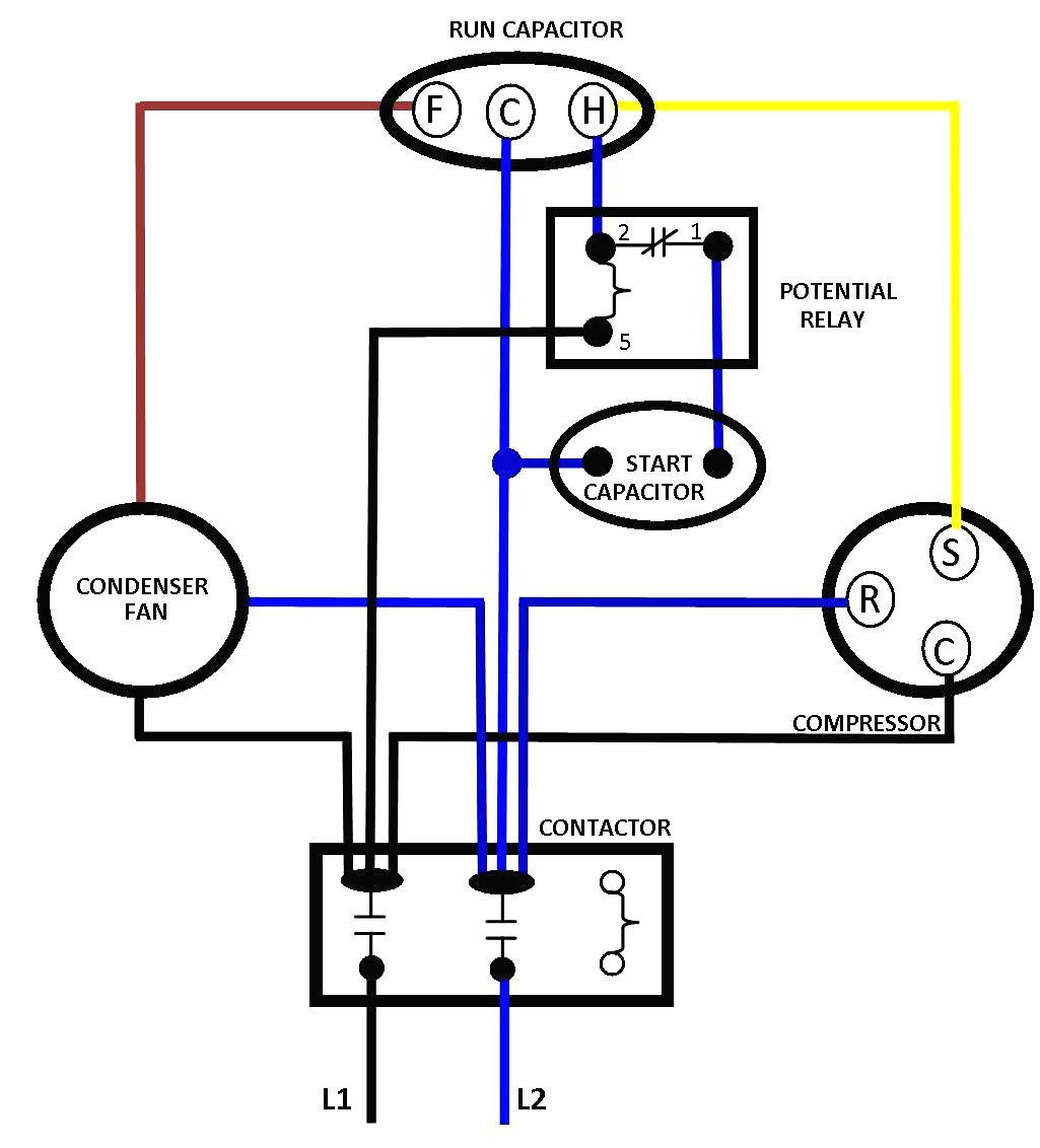
A C Compressor Capacitor Wiring Diagram
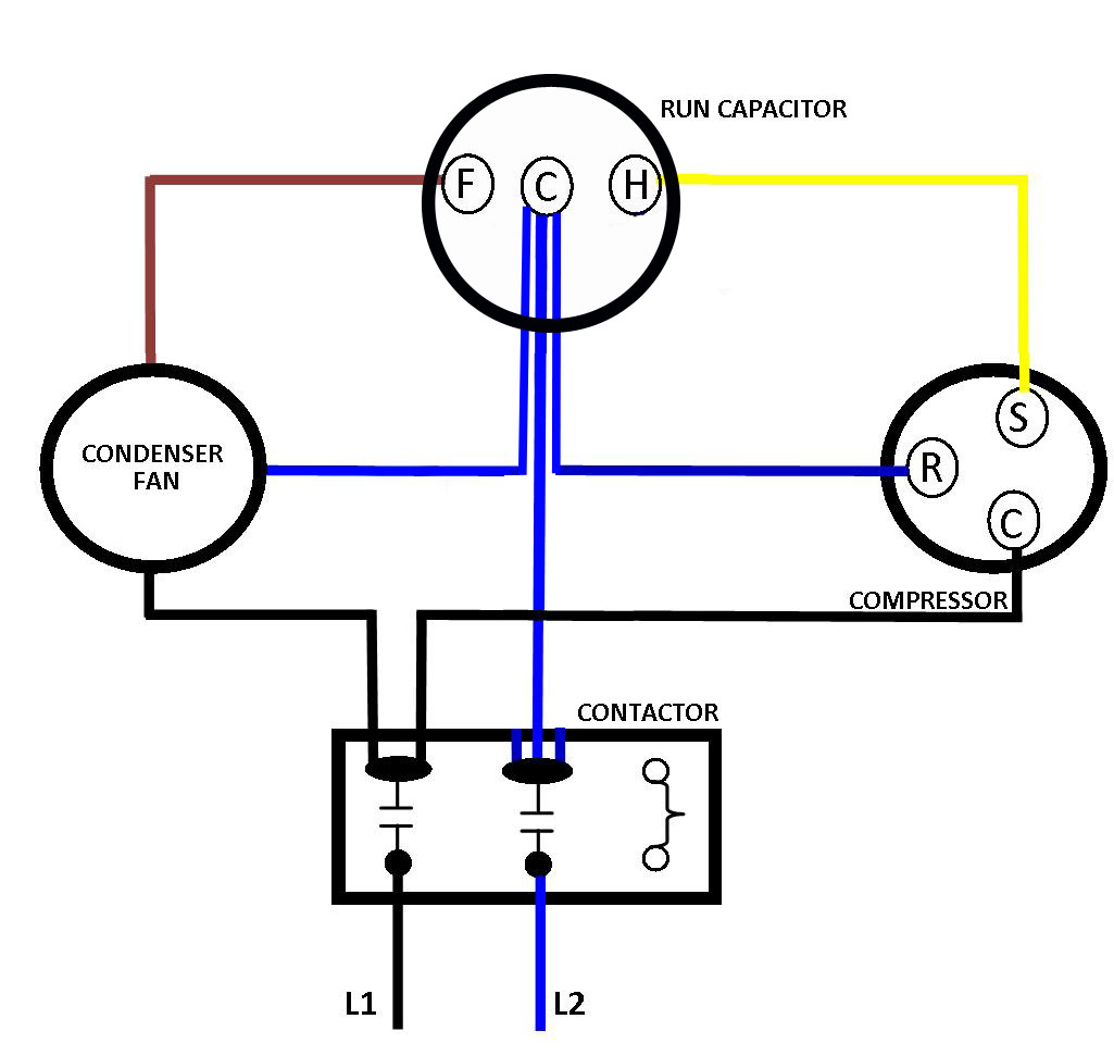
An AC compressor wiring diagram will include several components. The main components are the power source, the fuse, the thermostat, the motor, the pressure switch, and the fan motor. Additionally, wiring diagrams typically have a ground connection, a capacitor, and various other components such as relays and solenoids.
A C Compressor Wiring Diagram Wiring Diagrams Hubs Auto Ac
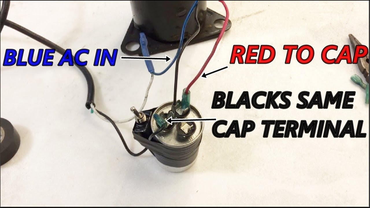
Step 3. Connect the red wire, leading to the capacitor, to the start terminal. The black wire, leading to the load side of the contactor, is connected to the run terminal. The white common line is connected in series with an overload switch that protects the compressor from overheating. The overload might be internally located in the compressor.

☑ How To Replace Electric Motor Capacitor
In conclusion, an air conditioner compressor wiring diagram can be an invaluable tool for any technician. Diagrams provide a detailed overview of the system's circuitry, allowing technicians to easily identify errors and carry out complex repairs. Familiarizing yourself with the diagram's symbols and keeping the diagram up to date can also help.
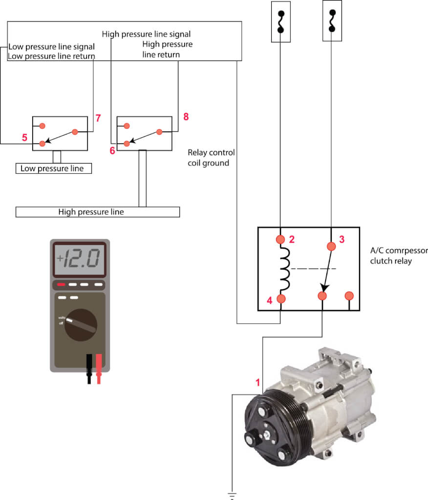
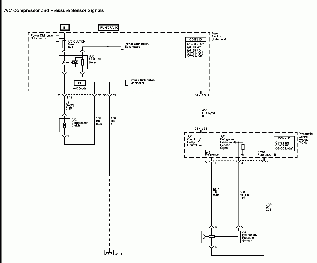
AC compressor won't run — Ricks Free Auto Repair Advice Ricks Free Auto
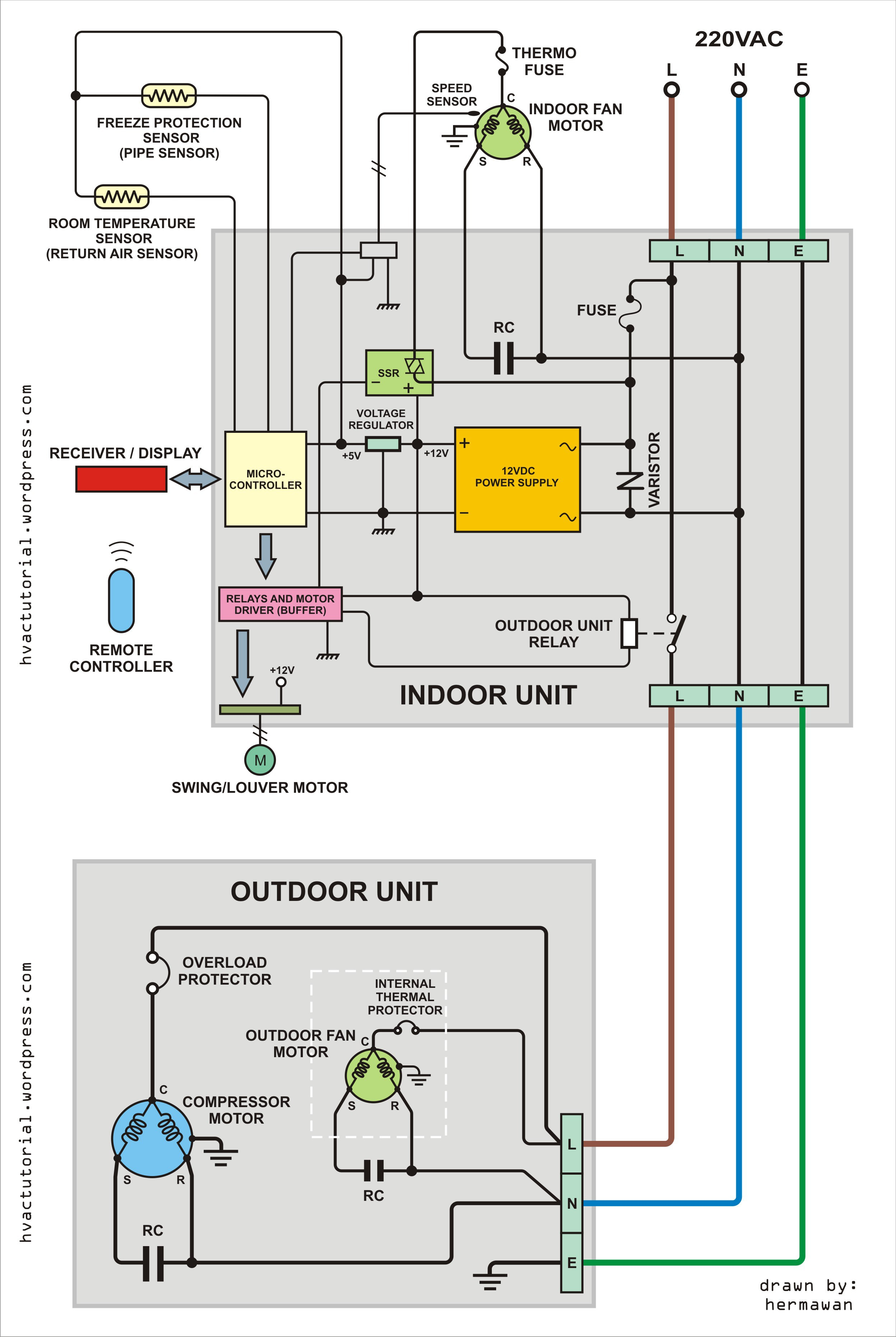
An ac compressor wiring diagram provides a detailed look at the components in your air conditioning system and how they interact with each other. A diagram shows connections between all of the parts that make up the unit, including the AC compressor, condenser, evaporator, thermostat, and all of the electrical components like relays and switches.