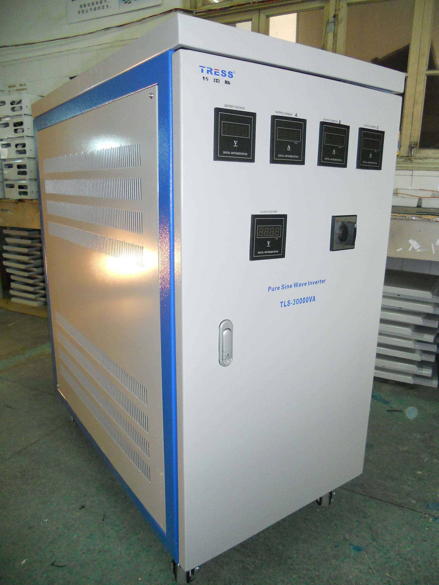
Three Phase Off Grid Solar Inverter 30KW Zhejiang Tress Electronic
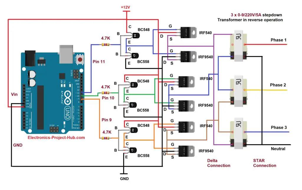
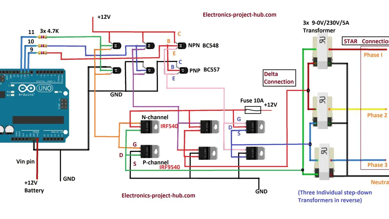
Three Phase Inverter Circuit Diagram. In this post we are going to construct a three-phase inverter circuit using Arduino and MOSFET. We will have a brief look at the three phase transformer working and we will construct a three phase transformer using three "single phase transformer" by combining the windings in delta and start connections.
Solar 3 Phase Inverter Circuit Electronic Circuit Projects
I can't think of many small three-phase loads apart from fractional-horsepower motors, and if you are driving a small motor, a VFD (that's a Variable Frequency Drive, not a Vacuum Fluorescent Display) might be more worthwhile; and if you have a large three-phase load, then 12V is not the place to start. C. Thread Starter.

China 3 PHASE SOLAR INVERTER Manufacturers, Suppliers, Factory 3
Single phase 3-11.4kW and and three phase inverters 9kW, 10kW, 20kW inverters - Use a standard straight-bladed screwdriver to connect the DC wires from the PV installation to the DC+ and DC- spring-clamp terminals, according to the labels on the terminals. Refer to the figures above. Three phase 14.4kW and 33.3kW inverters -
Should You Get A ThreePhase Solar Inverter? SolarQuotes Blog
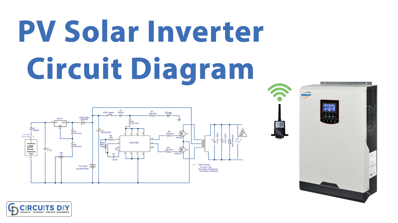
Solar Inverter Design: To easily understand the construction of a solar inverter lets discuss the following construction sample:-. According to the circuit diagram initially do the assembling of the oscillator part which consist of the small components & IC. It is finely completed by interrelating the part leads itself and fusing the joints.
sekretárka strecha odtieň solar panel inverter circuit design začiatok
Single Line Diagrams for Solis Inverters : Solis Solis-1P (2.5-6)K-4G-US Solis-1P (6-10)K-4G-US Solis- (25-40)K-US-SW Solis- (50-66)K-US-F-SW Solis- (75-100)K-5G-US Solis-125K-EHV-5G Solis- (185-255)K-EHV-5G-US RHI-1P (5-10)K-HVES-5G Single Line Diagrams for Solis Inverters Modified on: Thu, Jun 9, 2022 at 10:28 AM
Three Phase Inverter Circuit Diagram DIY Electronics Projects
If this equipment does cause harmful interference to radio or television reception, which can be determined by turning the equipment off and on, you are encouraged to try to correct the interference by one or more of the following measures: Reorient or relocate the receiving antenna. Increase the separation between the equipment and the receiver.
3 phase Solar Submersible Pump Inverter Circuit
Journal of Green Engineering (JGE) Volume-9, Issue-1, April 2019 Design and Implementation of Three Phase Micro Inverter Based PV Module S.Subramaniam1, B.Akash2, R.Vignesh3 and R.Mahalakshmi4 1,2,3,4Department of Electrical and Electronics Engineering, Amrita School of Engineering, Bengaluru, Amrita Vishwa Vidyapeetham, India.

Circuit Diagram Of Solar Power Inverter
The circuit diagram of three phase bridge inverter consists of minimum of 6 SCR and 6 diodes. Here a large capacitor is connected at the input side in parallel with Vs to make input DC voltage constant. This capacitor reduces the harmonics feedback to the source. The three-phase inverter is assumed to be star connected.
Simple 3 Phase Inverter Circuit Homemade Circuit Projects
Building a Solar Inverter If you are interested to build your own solar inverter then you ought to have a thorough knowledge of inverter or converter circuits, and regarding how to select solar panels correctly.
Three Phase Inverter Circuit Diagram DIY Electronics Projects
A three phase inverter is a device that converts dc source into three phase ac output . This conversion is achieved through a power semiconductor switching topology. in this topology , gate signals are applied at 60-degree intervals to the power switches , creating the required 3-phase AC signal. This type of inverter commonly employed in.
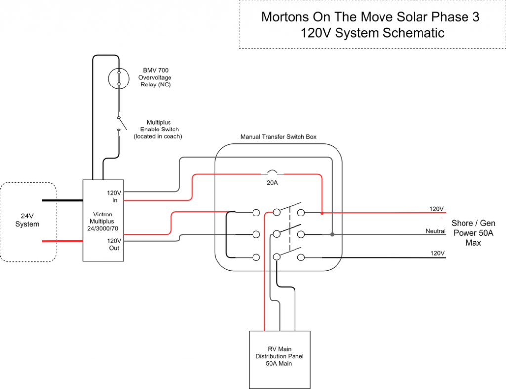
Solar Phase 3 The Inverter Mortons on the Move
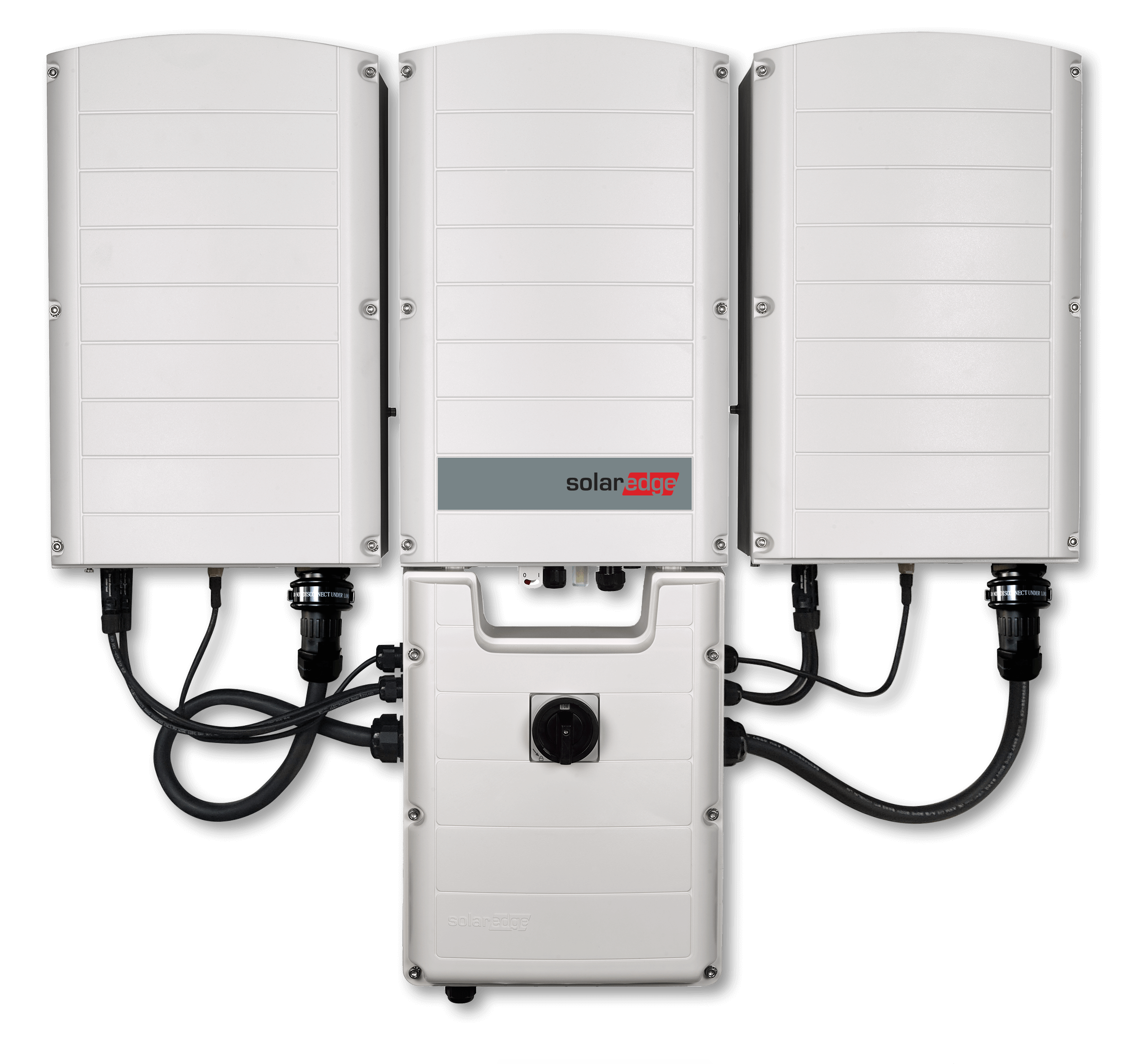
A SolarEdge PV system, shown in Figure 1 below, consists of three main elements: PV modules, power optimizers (dc to dc converters) located at each module, and a separate dc to ac grid interactive inverter which can be located at the array or at a remote location, e.g. near the main service entrance.
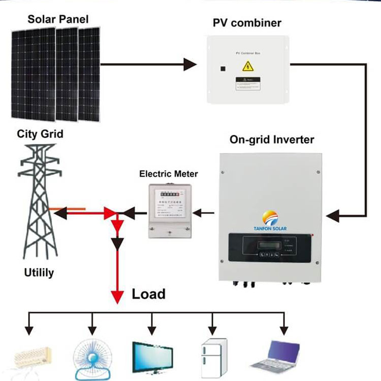
On grid solar inverter, Three phase solar inverter, 100kw solar
View the TI TIDA-01606 reference design block diagram, schematic, bill of materials (BOM), description, features and design files and start designing.. bidirectional three-phase three-level (T-type) inverter and PFC reference design TIDM-02002. Breakthrough technologies lead the solar power industry into the future: Jul. 27, 2018:
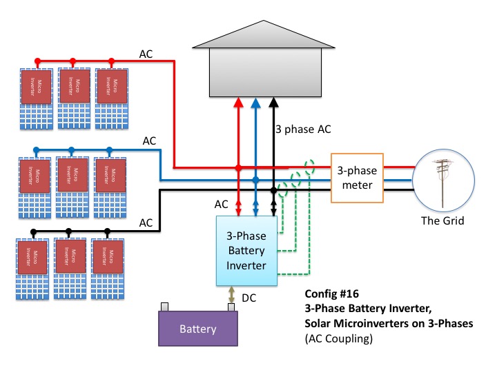
Don't Add Batteries To A 3Phase Home Before Reading This
Below is a three-phase inverter circuit diagram designed using thyristors & diode (for voltage spike protection) And below is a three-phase inverter circuit diagram designed using only switches. As you can see this six mechanical switch setup is more useful in understanding the 3 phase inverter working than the cumbersome thyristor circuit.
Are 3Phase Solar Inverters Needed? Compare Solar Quotes
Definition: We know that an inverter converts DC to AC. We have already discussed different types of inverters. A three-phase inverter is used to change the DC voltage to three-phase AC supply. Generally, these are used in high power and variable frequency drive applications like HVDC power transmission. 3 Phase Inverter

Inverter Drive Wiring Diagram
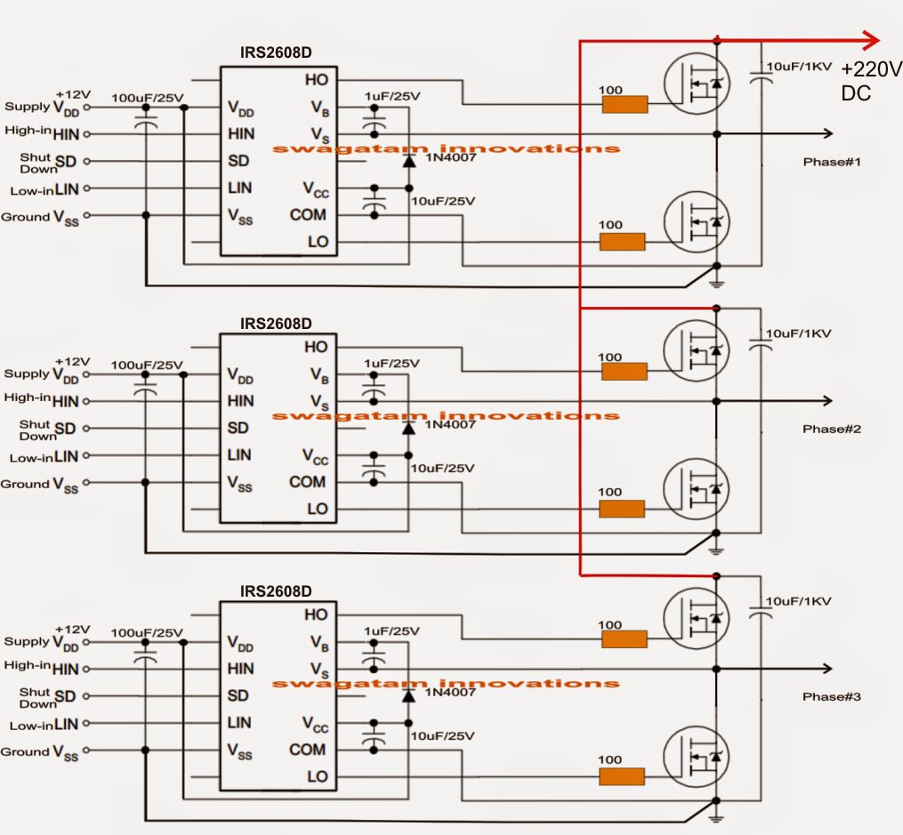
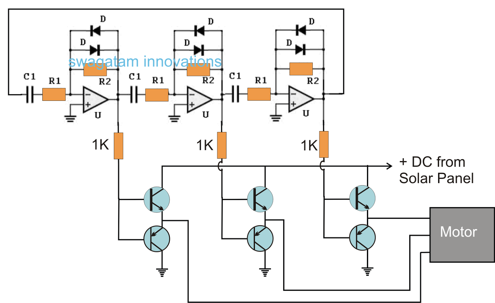
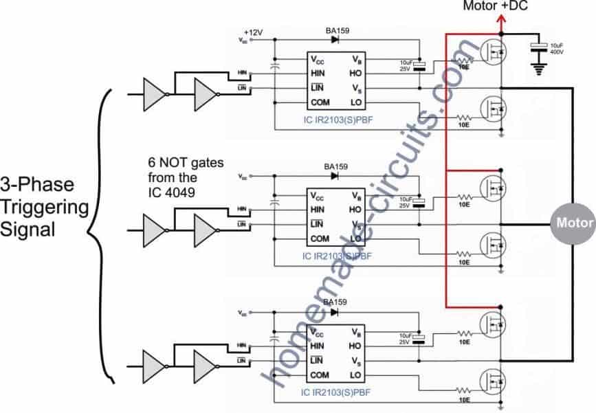
The 3 phase signal generator circuit The mosfet driver circuit The first diagram below shows the PWM generator stage, it may be understood with the following points: The Oscillator and the PWM Stage The IC 4047 is wired as a standard flip flop output generator at the rate of the desired mains frequency set by VR1 and C1.
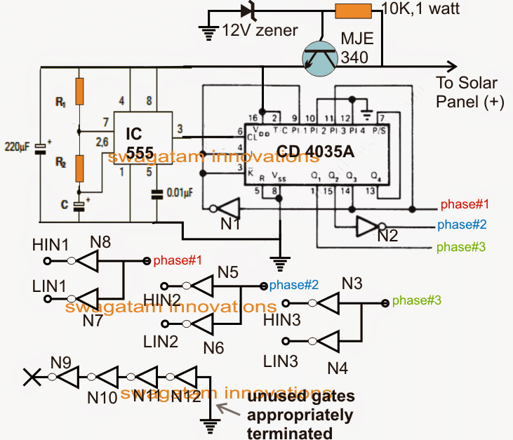
Solar 3 Phase Inverter Circuit
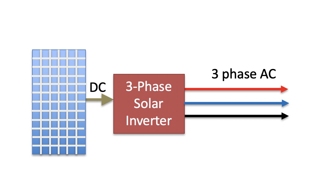
A 3-phase solar inverter converts DC power generated by solar panels into AC electricity just like any inverter. However, a three phase solar inverter does something extra, which is, it splits the AC into 3 chunks for a three phase supply. 3 phase solar inverters are reliable, efficient, and affordable.