ptc wiring diagram KonradNatalya
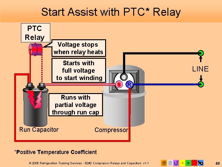
A PTC relay uses a positive temperature coefficient thermistor to remove the start winding and/or start capacitor from the circuit. A PTC thermistor is basically a resistor whose resistance increases on an increase in temperature. The circuit is wired so that the PTC thermistor is wired in series with the start winding of the motor (Fig. 1).
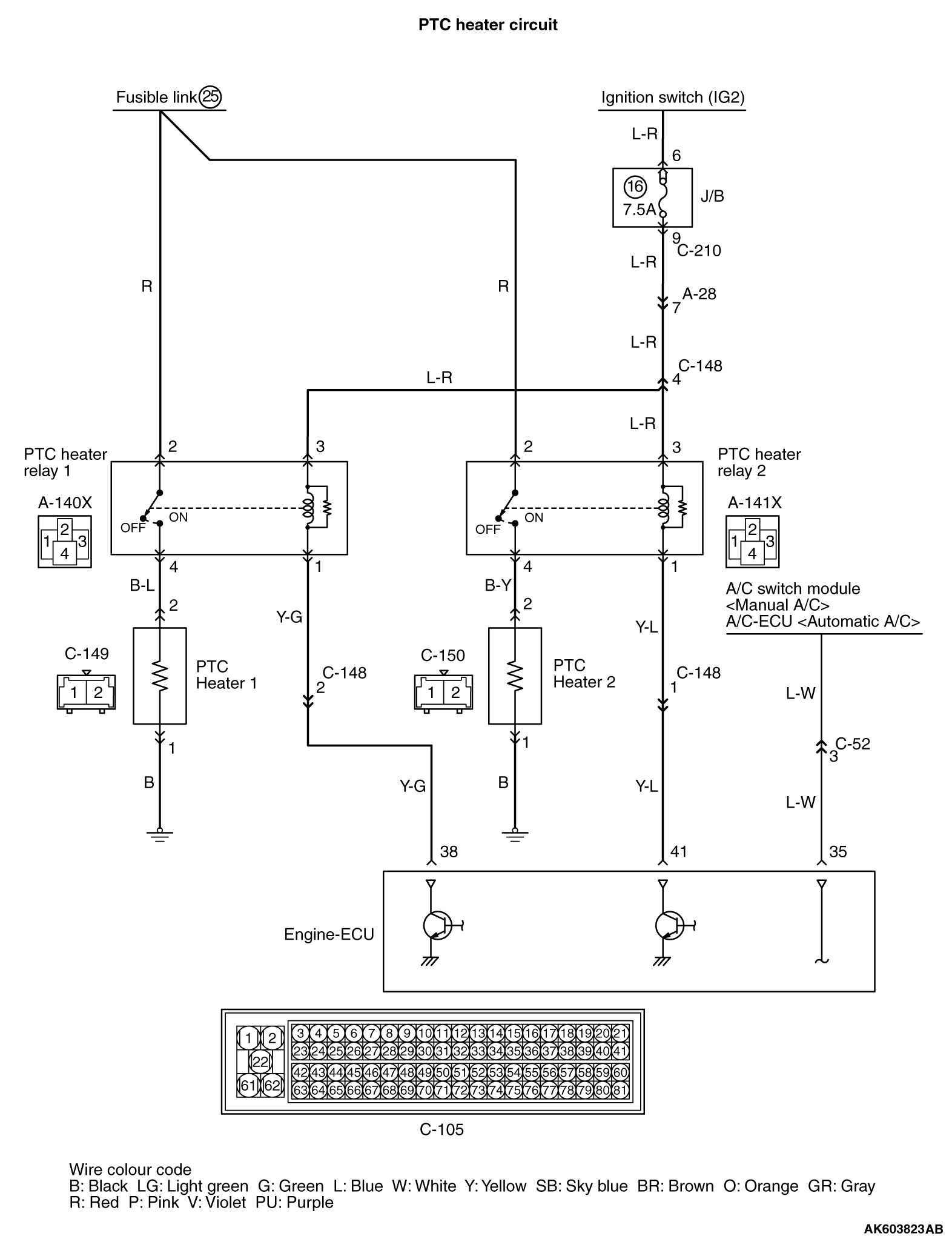
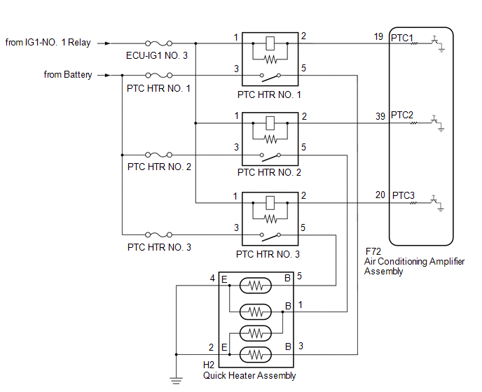
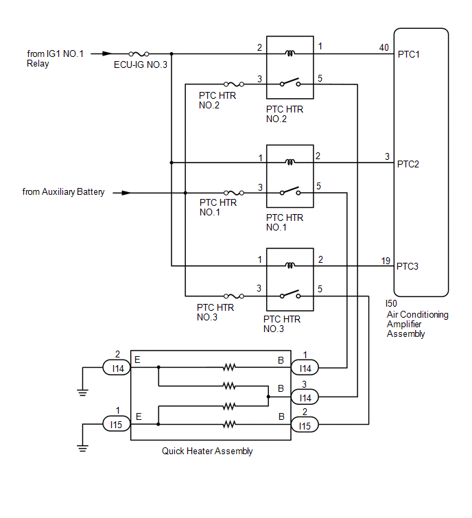
Inspection Procedure 24 PTC Heater Relay System
The most comprehensive refrigerator compressor start relay testing video on the internet. We show how to test a start relay for continuity and resistance, h.

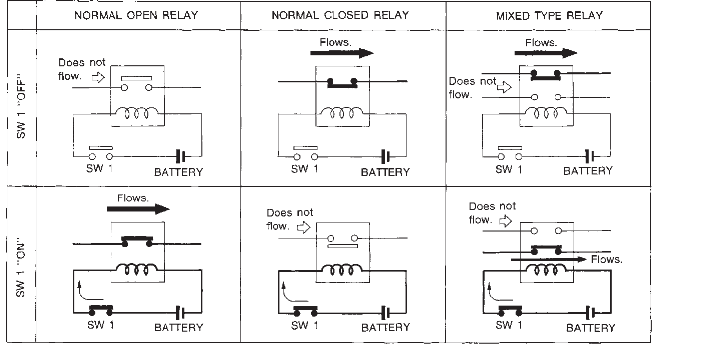
Relay Wiring Diagram and Function Explained ETechnoG
A PTC (Positive Temperature Coefficient) relay is a starting device for fridge compressors. It is responsible for powering the start winding for a brief moment to help start up the fridge compressor motor. If your fridge cannot start there is a high probability that the PTC relay is defective. This article presents how to test them to determine whether they need replacing.

JJREFRIGERACION EL RELE PTC + RELE ELECTRONICO
The PTC (Positive Temperature Coefficient ) Thermistor is Used to Help Start the Compressor. This Thermistor is Commonly used in Conjunction with a Start Cap.

Refrigerator Compressor 3 Different Way Connect current Relay PTC
If the reading on the multimeter is between 0 and 1 ohms, the relay is in good working condition. If the reading exceeds 1 ohm, replace the PTC relay. In other words, the relay should read O.L or 0 to 1 ohm. Before testing the relay, clean the device and all its sports to remove dust. Dust may interfere with the resistance reading, throwing it off.

ptc wiring diagram KonradNatalya
This video provides step-by-step repair instructions for replacing the PTC relay on a GE refrigerator. The PTC relay sends power to the start winding to star.
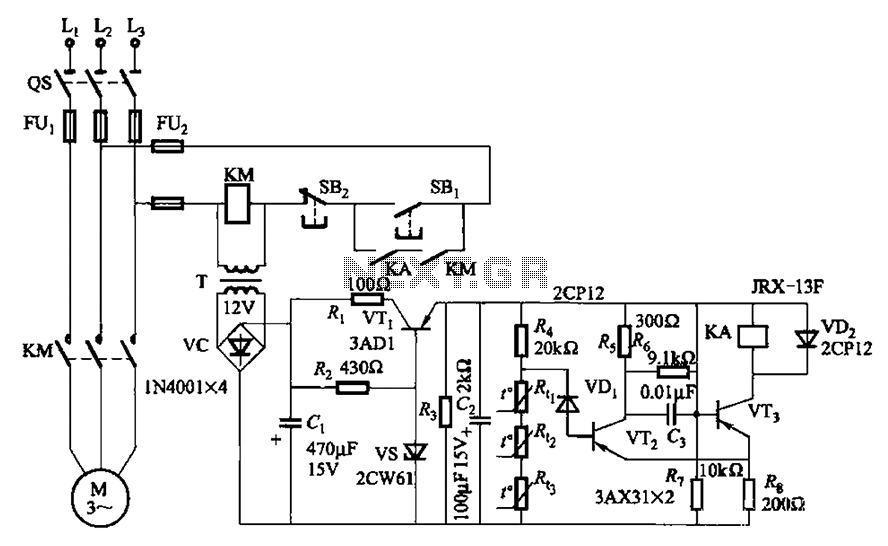
Threephase asynchronous motor PTC protection circuits under Motor
The wiring diagram for a refrigerator PTC relay typically consists of several components, including the relay itself, the compressor motor, the start capacitor, and the overload protector. Each of these components has specific connections that need to be made to ensure proper functioning. It is essential to carefully follow the manufacturer's.
PTC Heater Relay
Set your multimeter to read resistance in ohms (Ω) so you can easily test the PTC relay. Plug the end of the red probe into the positive (+) terminal and the black probe into the negative (-) terminal on the bottom of the multimeter so you can use them. [8] You can buy a multimeter from a hardware store or online. 3.

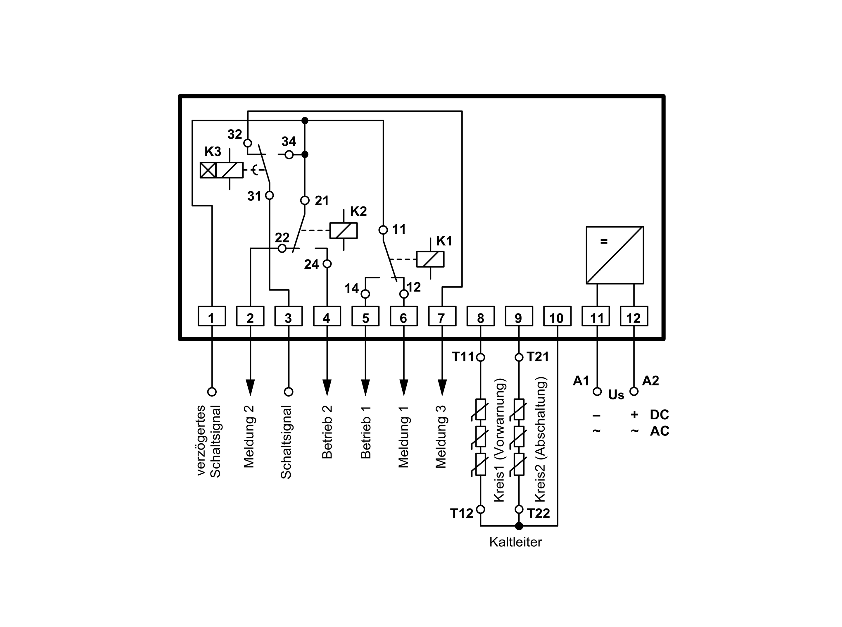
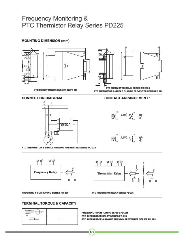
PTCThermistorRelay Type MSR220F ZIEHL industrieelektronik GmbH + Co KG
With the start capacitor we connect the ptc relay thermistor in series, which eliminates the start capacitor in the circuit. In many relay PTC compressor has a connection point for the operating capacitor and connect the capacitor in parallel with the relay, which helps better performance and compressor. ptc relay working principle, ptc relay.
Compressor Ptc Relay Wiring Diagram
The 3RN2 thermistor motor protection relays are designed in two widths: 17.5 mm This overall width is used for the 3RN2000 compact tripping relays with 1 changeover contact and with A1 jumpered contact root of the changeover contact and the 3RN2010-.C.30 with 1 NC contact and 1 NO contact.
ptc wiring diagram KonradNatalya
The circuit diagram below shows an example of an inrush current limiter (ICL) circuit, in which a PTC thermistor and a thyristor (or a mechanical relay) are used in combination. When the power switch is closed and the charging process starts, the uncharged capacitor is like a short circuit and therefore draws a very high inrush current.
ptc relay wiring diagram Wiring Diagram and Schematic
At ambient temperature, the values should be near those presented in the list below:Relay PTC- Relay PTC 8EA 1B1X - 2.8 to 5.2 Ω; - Relay PTC 7M4R7XXX / 8M4R7XXX / 8EA14CX- 3.8 to 5.6 Ω; - Relay PTC 8EA4BX / 8EA3BX / 8EA21CX - 3.5 to 6.5 Ω; - Relay PTC 8EA5BX - 14 to 26 Ω; - Relay PTC 7M220XXX / 8M220XXX / 8EA17CX - 17.6.

Patent EP0590592A1 Motor starting relay device having PTC thermistors
Compressor PTC relay working and uses in refrigerators or how to use capacitor start PTC relay with refrigerator compressor.. i have a frigidare chest freezer that wont run just clicks after its on for 1 min or so ordered new start relay and overload need a diagram of where the wires should be think someone else has messed with them. Reply;

Temperature protection using PTC and LM393 Electronic Circuit
The PTC (positive temperature coefficient) relay is directly connected in series with the secondary winding (start winding) and in parallel with the main winding of the motor. When AC 220V is applied to the two windings, a phase difference will be generated due to phase separation, thus forming an elliptical rotating magnetic field and generating a starting torque to drive the normal operation.
Find application of PTC thermistor Relay GIC India
Then at start, with PTC in series: If Zaux is low impedance, less than 10 % of RPTC then it can be ignored and IPTC at start = This closely approximates the condition for motors over 1/2 HP Fig. T-5 Fig T-6 Simplified voltage diagram of the PSC motor at operatingPTC speed. Note (1) I A (auxiliary current) leads I M (main current) by 80° to 90.

wiring diagram ptc relay
In this HVAC Service Training Video, I explain Step By Step How to Troubleshoot a Refrigerator Compressor that will not Start. I go over the Different Compon.