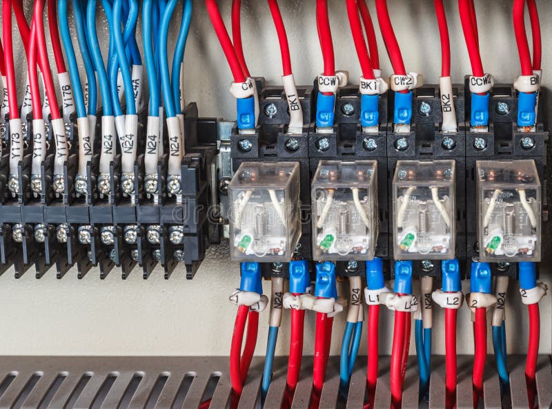
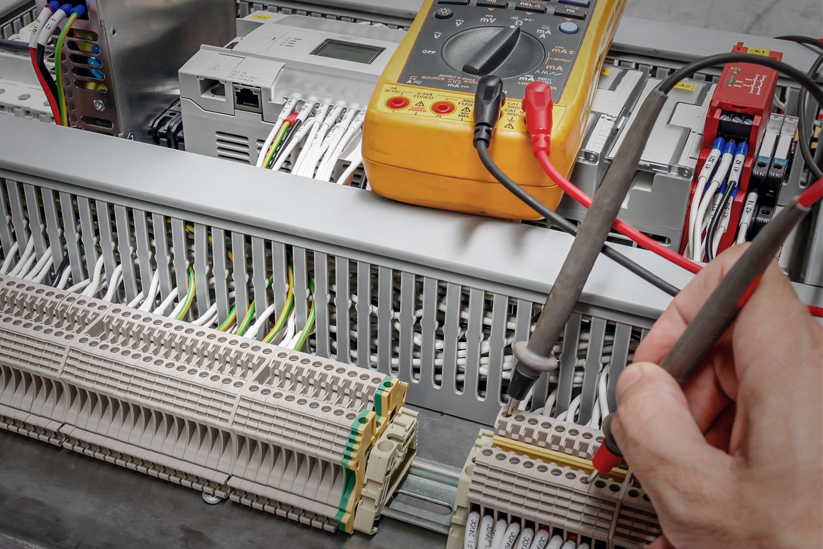
Wiring PLC stock photo. Image of ammeter, cubicle, electrical 71996202
Reading a PLC Wiring Diagram is one of the must-to-learn skills for every automation and electrical engineer. Despite different standards of these types of drawings, you'll learn using actual industrial drawings and some PLC wiring best practices.
siemens logo plc wiring diagram Wiring Diagram and Schematic Role
PLC wiring diagrams are graphical representations of the electrical connections and devices used in a PLC system. They provide a visual guide for technicians and engineers to understand how the different components are connected and how signals flow through the system.

instrumentation wiring diagram
A PLC panel is simply an electrical control panel consisting of electrical components which use electric power to control a variety of mechanical functions of industrial machinery or equipment. In order for industrial machinery and equipment to accomplish their various process goals, they require user-defined functions and well-organized control.
Plc Cable Wiring Diagram Wiring Diagram and Schematics
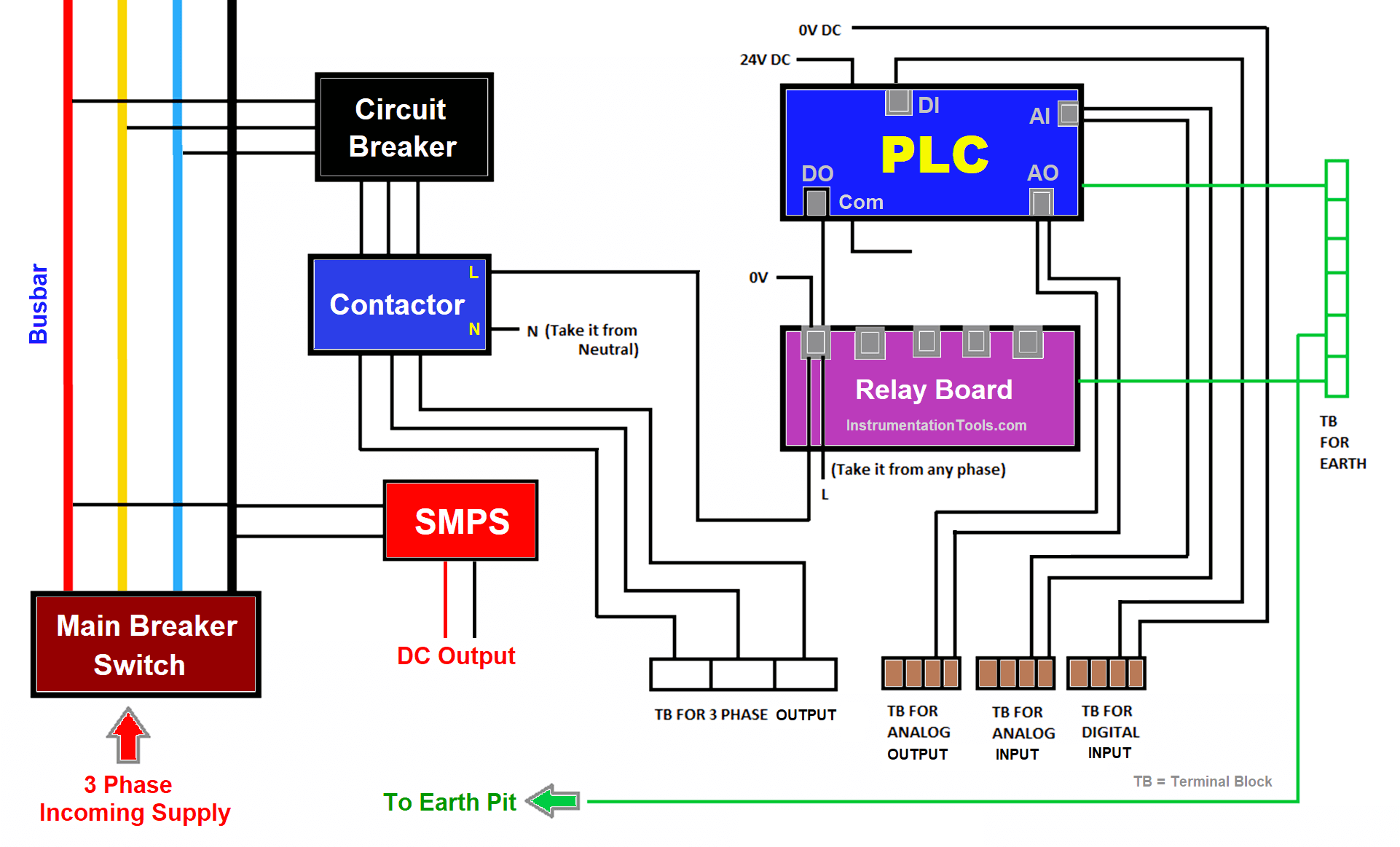
The wiring of a PLC ( Programmable Logic Controller) is a fundamental part of the installation and commissioning of automated control systems. PLCs are used to control various industrial processes and machines. The wiring connects the PLC to sensors, actuators, and other devices on the factory floor.

Wiring Diagram With Plc Wiring Digital and Schematic
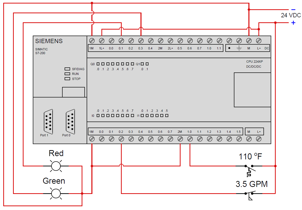
PLC Digital Signals Wiring Techniques by Editorial Staff Ina process plant, on/off control is done through the PLC or DCS. The below Figure is an overview of one discrete/digital (on/off) circuit, showing the entire process from the power supply through the sensor and on to the PLC. Table of Contents PLC Digital Signals Wiring Techniques a.
Ab Plc Wiring Diagram Caret X Digital
C'mon over to https://realpars.com where you can learn PLC programming faster and easier than you ever thought possible!===== Chec.
Ban genius sunset plc layout
Join us here, get awesome perks, and support us, all at once:https://www.youtube.com/c/upmation/joinRead the full blog post at https://upmation.com/plc-w.

How To PLC Wiring In Control Panel The Automization
Electrical wiring diagrams of a PLC panel In an industrial setting a PLC is not simply "plugged into a wall socket". The electrical design for each machine must include at least the following components. Transformers - to step down AC supply voltages to lower levels

automationplcwiring1 The Stiegler Company
How to install a PLC and how to do the PLC wiring? PLC / 4 minutes of reading A PLC is an industrial computer that is capable to do discrete or sequential logic in a factory environment. The PLC was developed to replace the mechanical relays, timers, and counters. The PLC is considered as the heart of the control system in an automated system.

Ann Cabling Plc Control Panel Wiring Diagram скачать программу
Join us here, get awesome perks, and support us, all at once:https://www.youtube.com/c/upmation/joinWhen you look at an industrial control panel wiring dia.

Siemens Plc S7 1200 Wiring Diagram Wiring Draw And Schematic
A wiring diagram gives the necessary information for actually wiring-up a group of control devices or for physically tracing wires when trouble-shooting is necessary. A line diagram gives the necessary informa- tion for easily following the operation of the various devices in the circuit. It is a great aid in trouble-.
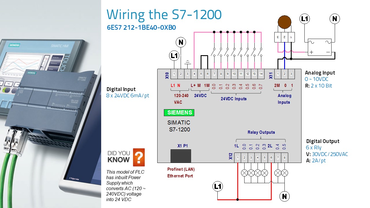
Siemens Plc S7 1200 Wiring Diagram Wiring Diagram
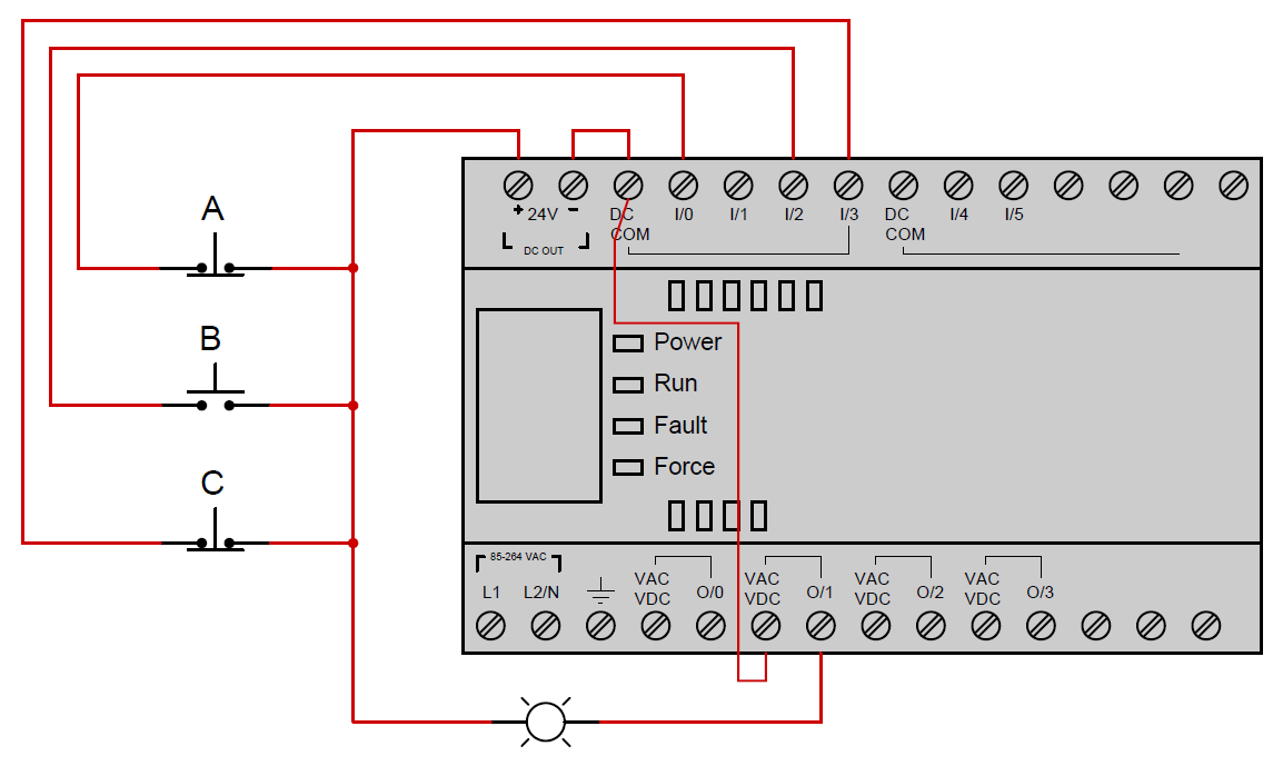
More Information This video explains the various terminals of PLC and its wiring fundamentals. It show's how to connect Inputs and Output to the PLC terminals.
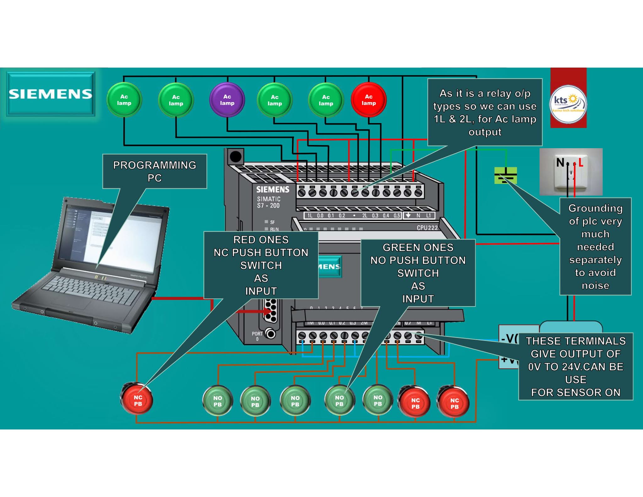
SIEMENS PLC WIRING S7200 PLC WIRING DIAGRAM Kavisa Tech Solutions
1. Ensuring System Reliability: Proper PLC control panel wiring is critical for ensuring the overall reliability of the system. Any loose connections, improper grounding, or incorrect wiring can lead to voltage fluctuations, signal interference, or even system failure.

Basic electrical design of a PLC panel (Wiring diagrams) EEP
Programmable Logic Controllers (PLC) are often defined as miniature industrial computers that contain hardware and software used to perform control functions.
automationplcwiring3 The Stiegler Company
Plc Wiring Diagram Examples: Explaining the Basics of Electrical Automation. Programmable logic controllers (PLCs) are some of the most important components in modern electrical automation systems. They allow for precise control of a wide range of devices and machines, leading to improved efficiency, accuracy and safety.

Allen Bradley Plc Wiring Diagram Wiring Diagram Networks
Wiring in a PLC control panel is a hectic job and requires a good understanding of PLC standards as well as electrical standards. Basically, before PLC was being started to be used in the market, wiring was the only method to provide control of a system.