Wireless Reversing Camera Wiring Diagram
A 5 pin reversing camera wiring diagram provides a visual representation of how the different components should be connected. The diagram typically includes pins for power supply, ground, video transmission, and control signals. It is important to consult the camera manufacturer's instructions for any additional details or requirements.
wiring diagram for reverse camera
Each colour indicates a different type of connection to the camera system. Knowing the wire colours and what they mean can help with the installation and troubleshooting of reverse cameras. The most common colours found in reverse cameras are: Red: Red wires indicate power connections. White: White wires are usually ground (earth) connections.
wiring diagram for car reverse camera
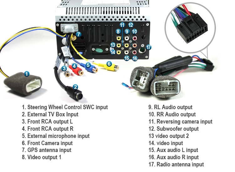
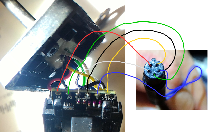
Posts: 1,113. Likes: 21. Received 385 Likes on 245 Posts. I'm not quite sure what you're asking for, but if you really just want a description of each wire that goes to that plug, here's a basic rundown: 1 - Fuse = Power. 2 - LIN Bus = Communication/Control (from BCM with just a standard rear view camera) 3 - Video signal "-" - (think speaker.
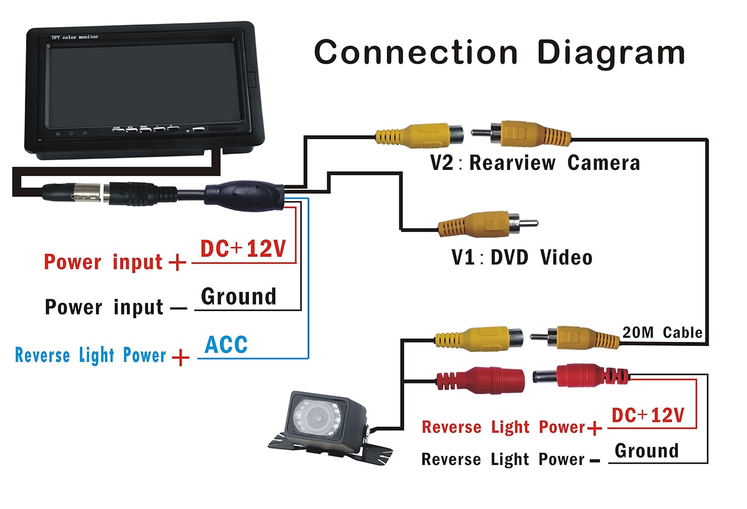
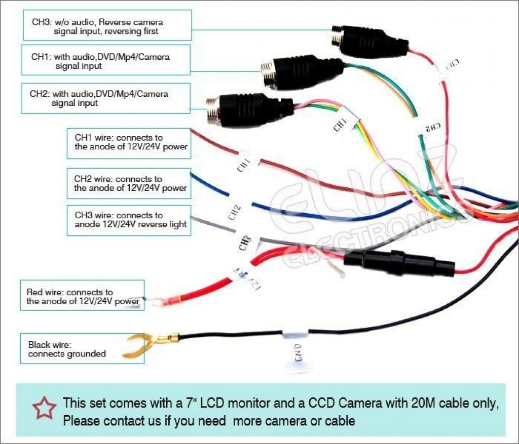
Tft Lcd Monitor Reversing Camera Wiring Diagram
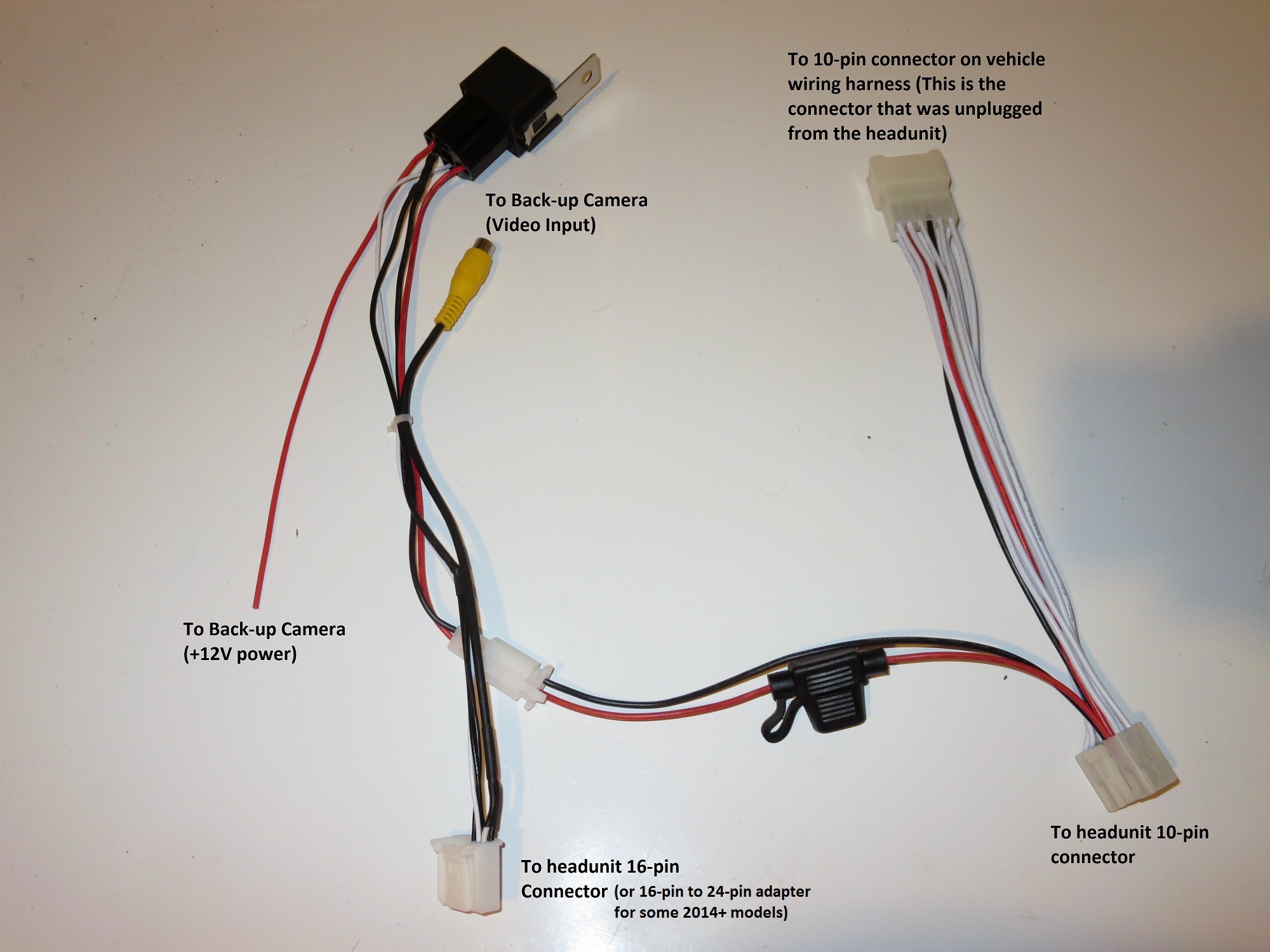
Creating adaptors for a reversing camera With more vehicles having a reversing camera fitted as standard we are seeing more and more people needing to replace these when they fail. If you have a 360 degree system or one built into a car then there are issues with replacing an existing factory fitted camera.
Car Reverse Camera Installation Diagram
The 5 pin reversing camera wiring diagram is a crucial tool that allows you to connect the camera to the power supply and the display unit in your vehicle. It provides a clear illustration of the required connections, ensuring that you install the camera correctly and avoid any electrical issues.

How To Wire A Reverse Cameras Reverse Camera Wiring Explained YouTube
See the 5 Pin Reversing Camera Wiring Diagram images below 5 Pin Reversing Camera Wiring Diagram, VL_3678 5 Pin Wiring Diagram Camera Schematic Wiring 5 Pin Reversing Camera Wiring Diagram, 5 Pin Reverse Camera Wiring Diagram - OUCAHM What is a Wiring Diagram?
5 Pin Car Camera Diagram
PRODUCT OVERVIEW Thank you for purchasing the SCA-RC51 Dynamic guideline reversing camera kit. The dynamic guidelines show the intended motion of the vehicle while reversing. This product is designed for easy DIY installation but does require some specific tools, and may require a qualified technician to install. PACKAGE COMPONENTS

5 Pin Backup Camera Cable Wiring Diagram Database
#1 Hi I have 4 pin back up camera already installed as seen in the first picture. I recently purchased a rear view mirror cam which comes with both front and back cameras. I want to use my existing 4 pin back up camera. Unfortunately the new pin out connector is 5 pins instead of 4.
5 Pin Reversing Camera Wiring Diagram
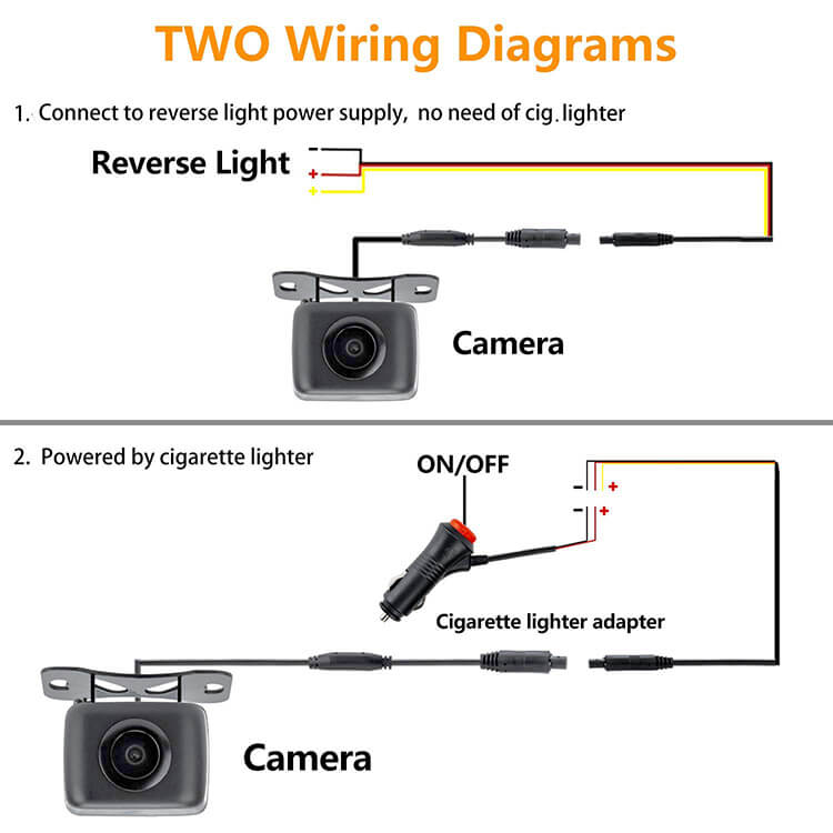
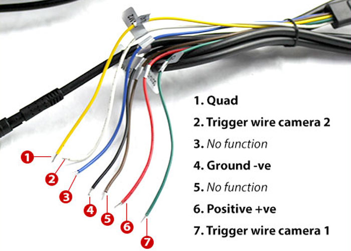
DUAL CAMERA KIT IMPORTANT NOTES: WIRING DIAGRAM 12V red male output plug is not (PART NO: P0501-0002N) Rev 1.02 - 7/12/2011 required for use White wire needs to be connected to the reverse light 12V+ as a trigger wire. Red wire is the power wire for the entire Auto Switching 11 Unit

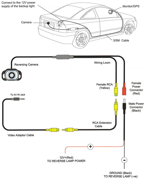
How to wire a Reverse Camera
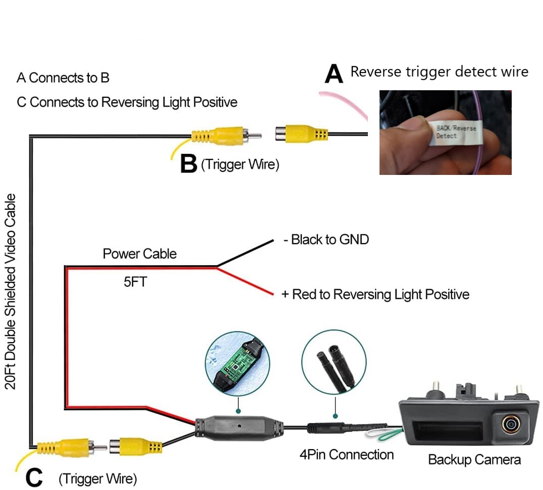
Feamal RCA (Yellow) + RCA Extension Cable ( Red: [12V + (Red) To backup lamp power and To reverse monitor/GPS Cable]) + Video Adaptor Cable Female Poer Connector (Red) + Male Power Connector (Black) GROUND (Black) To backup lamp (-ve) Rear view camere wiring images Backup camera trigger wires installation guide

5 Wire Reverse Camera Wiring Diagram diagramwirings
Sample Wiring Diagrams Assemble your tools and equipment for camera installation Sample Installations Testing time 1) The One Minute Explanation of How Backup Camera Installs Work Every backup camera installation follows roughly the same few steps: 1) First decide which type of backup camera you want.
Reverse Camera Wiring Colours Wiring Diagram and Schematics
Step 1: Gather the necessary tools Before starting the wiring process, make sure you have all the necessary tools at hand. This includes a multimeter, wire strippers, electrical tape, crimp connectors, and a wiring diagram specific to your vehicle's make and model. Step 2: Identify the reverse light wire

5 Pin Reverse Camera Wiring Diagram
A 5 Pin Reverse Camera Wiring Diagram is a schematic representation of the electrical connections and components needed to install and operate a reverse camera system in a vehicle. It provides a visual guide for technicians or DIY enthusiasts to understand how the camera, monitor, power supply, and other hardware should be connected to ensure.
Reverse Camera Wiring Diagram Toyota
2K 448K views 5 years ago Quick video explaining how a reverse camera is used. This just gives you a little insight into what each section does, making it a little easier to understand then.

5 Pin Reversing Camera Wiring Diagram
The wiring diagram for a 5-pin reversing camera typically includes connections for power, ground, video signal, and sometimes additional features such as audio or parking lines. It is important to follow the specific wiring diagram for your camera to ensure proper installation and functionality.
reverse camera wiring
Connect pin 30 (blue wire) to battery power source. Pin 87 (red wire) goes to camera power wire leading to head unit. Pin 85 (white wire) goes to reversing light power wire. Pin 86 (Black wire) to ground. reverse camera with relay wiring diagram Thanks our customer Gregory Davis who provided the above photo from USA.